
Proportional Solenoid vs. On/Off Solenoid: Force-Stroke Linearity, PWM Dither, and Hysteresis Guide
Compare proportional solenoid vs on/off solenoid behavior, force-stroke curves, dither and hysteresis. Use the RFQ checklist to review your actuator design.
Selection answer: Choose an on/off solenoid for binary switching. For continuously variable force or intermediate spool positions, evaluate a proportional solenoid with a specified force-stroke range and a current-regulated driver. Add dither and position or process feedback when the selected valve and application require them; no universal hysteresis percentage follows from the actuator type alone.
Planning a custom proportional valve or electromagnetic actuator? Contact our engineering team to review your stroke, force-current curves and driver parameters for a custom electromagnet or solenoid assembly.
Article date / technical review: 2026-11-04. Scope: Global, English-language engineering and procurement guidance for DC proportional solenoids and on/off actuators in industrial hydraulic, pneumatic and mechanical systems. Application examples do not establish medical-device or automotive qualification. Not covered: Rotary torque motors, permanent-magnet voice-coil actuators, and AC line-voltage contactors. Calculations and diagrams are illustrative analysis, not measured product performance or customer test results. Confirm ratings and acceptance limits for the complete valve-driver assembly.
1. Executive Summary: The Gap Between Binary Switching and Continuous Actuation
Electromagnetic actuators switch valves, modulate pressure and move mechanical loads. An on/off actuator is usually selected to reach an end position reliably. A proportional actuator is selected for a controlled force-current relationship across a defined working stroke. The distinction matters when a buyer needs metering rather than simple opening and closing.
A variable PWM duty cycle alone does not establish proportional performance. Three checks determine whether the assembly will behave predictably:
- Stable equilibrium: Compare magnetic force with the spring and external load throughout travel. A steep force gradient can cause pull-in before the desired position is reached.
- Reversal behavior: Measure increasing and decreasing commands. Friction, magnetic history and fluid forces can produce different outputs at the same input.
- Thermal behavior: Check winding current and driver headroom when hot, not only coil voltage when cold.
This guide connects those checks to an RFQ, a bounded thermal calculation and a commissioning procedure. It does not rank actuator families by unsupported accuracy, service-life or purchase-price averages.
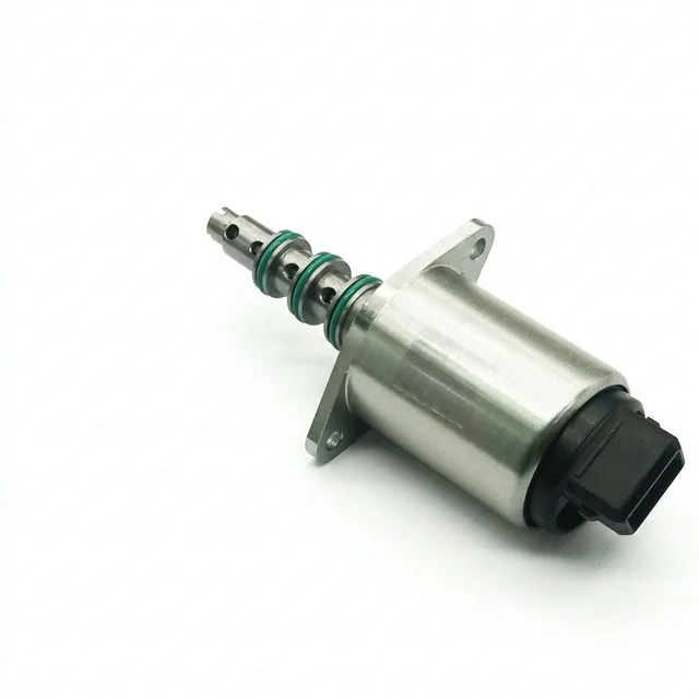
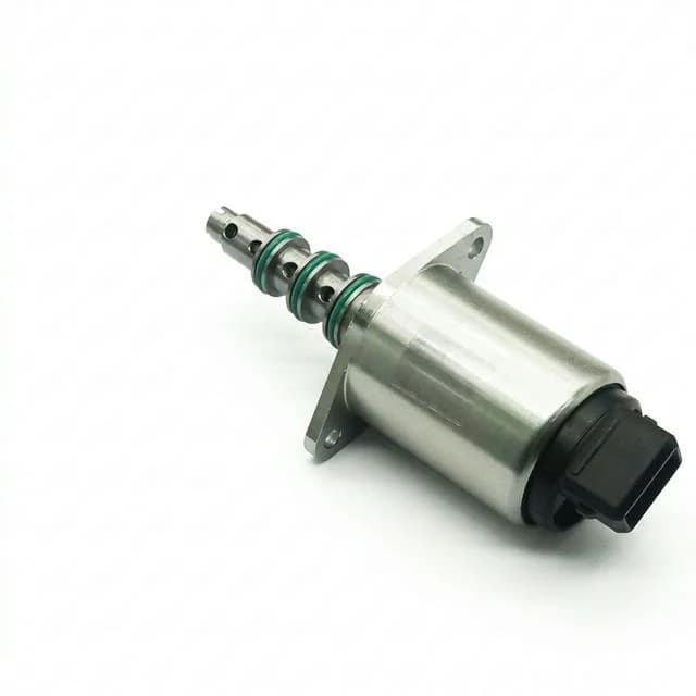
Figure 1: Proportional solenoid assembly from the product image library. Appearance does not establish pressure rating, force linearity or hysteresis; request the corresponding part drawing and test curves.
2. Electromechanical Comparison: On/Off vs. Proportional Solenoids
Compare the complete actuator, spring, load and electronics. A catalogue label is not a substitute for curves measured under stated conditions.
| Evaluation dimension | On/off solenoid | Proportional solenoid | Procurement and engineering check |
|---|---|---|---|
| Primary function | Switching between end positions | Variable force; intermediate position with a suitable load/spring | Define whether the output is state, force, position, pressure or flow. |
| Force-stroke curve | Often rises strongly as the gap closes | Relatively flat over a specified control stroke | Request curves at several currents, including stroke limits. |
| Magnetic geometry | Optimized for pull-in and holding | Shaped pole and flux paths for the required curve | Qualify measured performance rather than prescribing one pole shape. |
| Drive method | DC switching, PWM or peak-and-hold | Usually regulated current; dither when appropriate | Specify mean current, ripple, voltage range and current limits. |
| Hysteresis | Depends on actuator and mechanism | Depends on actuator, valve, driver and test procedure | Name the measured output, normalization and sweep conditions. |
| Thermal behavior | Fixed voltage allows current to vary with resistance | Current regulation compensates until voltage headroom runs out | Verify hot resistance and minimum supply voltage together. |
| Bearings and guidance | Selected for switching duty and load | Friction and side loads affect small-signal behavior | Test in the intended orientation with the actual linkage. |
| Life and wear | End-stop impacts may matter | Dither motion and contamination may matter | Request endurance evidence at the specified load and duty. |
| Total installed cost | Include power switching and protection | Include amplifier, tuning and any feedback | Compare actual quotations and integration work; no universal cost multiple applies. |
3. The Physics of the Force-Stroke Profile: Why Pole Geometry Matters
For an ideal, unsaturated magnetic circuit dominated by one uniform air gap, a useful screening approximation is:
F ≈ B² × A / (2 × μ₀) ≈ μ₀ × N² × I² × A / (2 × g²)
Here F is force in newtons, B is gap flux density in tesla, A is effective pole area in square meters, N is turn count, I is current in amperes and g is the remaining gap in meters. μ₀ is approximately 4π × 10⁻⁷ H/m. This model neglects leakage, fringing and iron reluctance; it cannot predict a real actuator near saturation or at a nominally closed gap. The inverse-square approximation is not an exponential law, and real force does not become infinite as the gap closes.
Use a separate coordinate, s, for pull-in displacement. As s increases, the remaining gap g decreases. A conventional actuator can therefore develop an increasing force gradient during pull-in. For a simple quasi-static equilibrium to be locally stable, the opposing spring/load force must increase with s faster than the magnetic force does. If that condition is lost, the armature can snap to an end stop. Intermediate positions are not mathematically impossible for every on/off actuator, but they cannot be assumed from PWM duty cycle alone.
How a Proportional Magnetic Circuit Helps
Designers shape pole profiles and flux paths, sometimes using controlled saturation, to reduce the force gradient over a defined control stroke. Geometry varies by product; a conical pole and a particular sleeve are not universal requirements. The Geeplus proportional-solenoid technical guide describes the control-stroke concept and the use of an opposing spring.
For a flat-force approximation and an external load that opposes pull-in:
s ≈ [Fmag(I) − Fpreload − Fexternal] / k
This is an equilibrium estimate, not a position guarantee. The spring rate k must use units consistent with displacement. Friction, varying flow forces, temperature and the ends of the control stroke change the result. Ask the supplier for force versus stroke at several currents and force versus current at several positions; a flat force-stroke curve does not by itself prove force-current linearity.
4. Visualizing Force-Stroke and Hysteresis Behavior
These qualitative diagrams explain curve shape and reversal behavior. They are not to scale, contain no measured force or stroke values, and do not establish a product rating. The first uses pull-in displacement increasing toward the closed gap; the second shows output differences at the same current.
Diagram 1: Force vs. Stroke Profiles Under Varying Control Inputs
Diagram 2: Hysteresis Loop With and Without PWM Dither Injection
5. The Mechanics of Hysteresis and the Role of Dither
A hysteresis curve compares increasing and decreasing input sweeps under the same test conditions. Distinguish force-current hysteresis at a fixed plunger position, position-current hysteresis, and flow-current hysteresis. A percentage from one cannot be substituted for another.
Mechanical friction resists motion and reverses direction when the plunger reverses. Static friction can delay initial movement and cause a jump when the mechanism breaks free. Bearings, seals, alignment, lubrication and contamination all affect this behavior. Magnetic material also retains some magnetization, so force can depend on magnetic history. Neither contribution has a universal share of the total error.
Dither adds a controlled oscillation to the mean current command. When it produces suitable small movements, it can reduce the effect of stiction. It does not remove all friction, repair binding, or eliminate magnetic hysteresis. The required motion and achievable improvement must be measured on the assembled valve. A supplier claim such as “3% hysteresis” is incomplete without the measured output, full-scale definition, temperature, sweep rate and driver settings.
6. Engineering Dither: Frequency, Amplitude, and Tuning Matrix
PWM switching frequency and dither frequency serve different purposes. PWM switches the power stage; coil inductance filters its current ripple. Dither is a deliberate modulation of the command. Some drivers use low-frequency PWM ripple as dither; others superimpose a separate waveform on a faster current-control loop. Check how the selected driver implements both.
Start with the valve and driver manufacturers' settings. A generic frequency or a percentage selected only from armature mass is not a validated recommendation. Electrical response, mechanical dynamics, seals and fluid conditions all matter. Excessive output motion can cause pressure ripple, noise and wear, while insufficient motion may leave stiction largely unchanged.
Define Amplitude Before Comparing Settings
Specify whether amplitude means peak, peak-to-peak or RMS, and whether a percentage is relative to rated current or the current command. For illustration, 4% peak-to-peak of a 1.5 A reference is 60 mA peak-to-peak, or ±30 mA for a symmetric waveform. This arithmetic is not a suggested setting. Near zero current, clipping a unipolar waveform changes the mean; near maximum current, its peaks may exceed the coil or driver limit.
| Tuning stage | Hold constant | Adjust or measure | Acceptance question |
|---|---|---|---|
| Documentation review | Valve and coil part numbers | Approved PWM and dither ranges; amplitude convention | Are driver settings compatible with this valve? |
| Electrical baseline | Mean command and test temperature | Current waveform using a suitable current probe or shunt | Does the actual ripple match the command? |
| Reversal baseline | Load, fluid and sweep rate | Increasing and decreasing output curves | Which error is being reduced, and how is full scale defined? |
| Frequency trial | Approved amplitude and mean current | Change frequency within supplier limits | Does hysteresis improve without excess output ripple? |
| Amplitude trial | Selected frequency | Increase amplitude within approved limits | Do noise, current peaks or heating exceed acceptance limits? |
| Environmental trial | Accepted electrical settings | Repeat cold/hot and at required pressure/load extremes | Does the tuning remain acceptable throughout the operating envelope? |
| Release record | Final hardware and firmware | Save settings, waveforms, curves and conditions | Can production reproduce and verify the result? |
Use a time-resolved measurement with sufficient bandwidth; a single RMS reading cannot show waveform clipping or separate carrier ripple from dither. Analog Devices CN0415 provides an example of monitored solenoid driving with programmable dither, rather than a universal tuning schedule.
Before selecting hardware: use the proportional-solenoid valve fit checker to organize load and driver requirements, then request the selected valve's actual curves and approved settings.
7. Electrical Driver Design: Thermal Drift and Voltage Headroom
At unchanged supply voltage and duty cycle, winding current changes as resistance changes. The following illustrative calculation uses a copper resistance coefficient of approximately 0.00393 per °C near 20°C. The assumed 80°C winding rise is an input, not a predicted temperature or an observed warm-up time.
Assume a 24 V supply, 16.0 Ω winding at 20°C and 80% PWM duty. For steady continuous current, negligible switch/diode drops and a recirculating driver:
- Cold mean current:
I20 ≈ 24 × 0.80 / 16.0 = 1.20 A. - Resistance at an assumed winding temperature of 100°C:
R100 ≈ 16.0 × (1 + 0.00393 × 80) = 21.03 Ω. - Hot mean current at unchanged duty:
I100 ≈ 24 × 0.80 / 21.03 = 0.913 A. - Relative current reduction:
1 − 0.913 / 1.20 ≈ 23.9%.
This simplified model neglects switching losses, changing inductance and detailed freewheel behavior. It does not establish an equal percentage change in force or flow: use the actual force-current curve and valve transfer characteristic.
Current Feedback Has a Supply Limit
A current-regulated amplifier measures winding current and changes the drive to follow the command. This reduces drift caused by resistance changes while sufficient voltage and thermal capacity remain available.
In this same example, maintaining 1.20 A when hot needs approximately 1.20 × 21.03 = 25.24 V across the winding before driver losses. A 24 V driver cannot deliver that continuously without an appropriate boost stage. Even at 100% duty, the ideal hot-current ceiling is only 24 / 21.03 ≈ 1.14 A. A current-control label alone therefore cannot guarantee the original setpoint.
For procurement, compare minimum bus voltage against maximum hot winding resistance, commanded current, cable drops and driver losses. For response time, also allow voltage to change current against inductance; steady-state headroom alone is insufficient. Ask for current-loop accuracy, ripple, compliance voltage and recovery behavior rather than assuming instantaneous compensation.
Thermal qualification must use RMS current. With zero-mean ripple, approximate winding dissipation is P ≈ R × (Imean² + Iripple,rms²). Dither adds heating even when mean current is unchanged. A regulated driver can maintain current while the coil overheats, so insulation class, allowed winding temperature and actual duty cycle remain separate limits.
8. Open-Loop vs. Closed-Loop Position Control
“Open-loop” needs a named variable. A solenoid can have a closed current loop while its spool position remains open-loop. In that arrangement, position follows the balance of magnetic force, return spring, friction and external load. It can be adequate when the resulting errors remain within the application tolerance across the specified conditions.
Position open-loop:
Command → Current regulator + optional dither → Solenoid + spring/load → Position

Position closed-loop:
Position command → Position controller → Current regulator → Solenoid + load
                         ↑                                      |
                         └──────── Position sensor ─────────────┘
Use an LVDT, inductive sensor, Hall sensor or another suitable transducer when measured spool-position errors require feedback. Define sensor range, resolution, temperature behavior, mounting and control-loop stability. Feedback cannot overcome unlimited load, a jammed spool or insufficient current/voltage capacity. A general bandwidth guarantee cannot be inferred from adding an LVDT.
Spool position is also not the same as flow or pressure. A valve at the same opening can pass different flow at different pressure drops. If the process requirement is flow or pressure accuracy, assess whether a process sensor and outer loop are needed. Select the least complex architecture that meets measured system requirements, and specify de-energized behavior and fault response alongside normal control performance.
9. Troubleshooting and Diagnostics Matrix
Compare electrical command, actual coil current and the required mechanical or fluid output. A symptom can have several causes; do not identify a driver topology from current drift alone.
| Observed symptom | Possible causes | Verification | Corrective action |
|---|---|---|---|
| Jerky small movements | Stiction, binding, unsuitable dither or deadband | Compare current waveform and slow reversal output sweeps | Correct binding and alignment; tune only within approved dither limits. |
| Buzzing or pressure ripple | Excessive modulation, mechanical resonance or supply ripple | Correlate current, vibration and pressure waveforms | Adjust approved settings and isolate the source rather than masking noise. |
| Output drifts when hot | Current drift, voltage saturation, spring/load or fluid changes | Log current, winding temperature, supply voltage and output together | Restore driver headroom or correct the identified thermal/load cause. |
| Armature snaps to end stop | Incompatible force gradients, wrong actuator, broken spring or excess command | Compare part number and measured load/force curves | Match actuator, spring and load; enforce command limits. |
| Driver or coil overheats | Excess RMS current, switching losses, duty or inadequate cooling | Measure RMS current, temperatures and driver fault status | Check component ratings, thermal design and approved switching/flyback behavior. |
| Hysteresis remains high | Side load, contamination, seals or magnetic history | Compare loaded/unloaded response using the supplier's service procedure | Repair alignment or contamination problems; use the valve-specific cleanliness requirement. |
Before mechanical inspection, isolate electrical power, release fluid pressure and secure stored spring energy. Do not detach a spring or open a pressure boundary on an energized assembly. Generic tuning cannot replace the manufacturer's service procedure.
10. Engineering and Procurement Specification Checklist
Send the following information with the RFQ. Values below illustrate how to write a requirement; they are not ratings of the pictured product.
- Working stroke and force: Define the displacement datum and usable interval, plus minimum force across it at specified currents and temperatures. An example requirement is at least 35 N throughout a stated 4 mm control interval. Include preload, spring rate, external loads and mounting orientation.
- Linearity and hysteresis: State the controlled output and reference span. For an output-normalized test, define hysteresis as the maximum rising/falling output difference at equal measured current divided by the specified full-scale output span. Name the sweep rate, settling time, temperature, load, pressure and dither settings. Use a separately defined best-fit or end-point reference for linearity error.
- Electrical and thermal envelope: Provide bus minimum/nominal/maximum, hot and cold resistance, current command range, RMS/peak limits and driver losses. Specify maximum winding temperature and ambient conditions separately. An insulation temperature class is not an allowable temperature rise or proof of whole-device approval.
- Dynamic response: Define the current or output step, starting operating point, load, pressure, measurement bandwidth, settling band and allowable overshoot. A 10–90% rise time without an identified output is ambiguous.
- Fluid and pressure boundary: Identify wet or dry armature operation, media, viscosity/temperature range, seals, cleanliness, operating pressure, proof test and applicable application qualification. Do not infer pressure compatibility from external appearance.
- Interfaces and fault behavior: Provide the envelope drawing, connector, mounting loads, ingress requirement and return-spring arrangement. State the required de-energized position and behavior after sensor, driver or supply failure.
- Acceptance evidence and commercial scope: Request traceable sample curves, test conditions, agreed production tolerances, endurance criteria, included driver/feedback hardware, lead time and quotation assumptions. Record unknown inputs rather than substituting catalogue averages.
For electrically modulated four-port hydraulic directional flow-control valves, ISO 10770-1:2009 provides a relevant performance-test framework. It is not a universal compliance claim for a bare solenoid, gas valve or pressure-control valve. Agree the applicable method with the supplier. DIN VDE 0580:2011-11 addresses general electromagnetic-device requirements; its catalogue scope does not certify the selected assembly.
11. Frequently Asked Questions (FAQ)
What is the fundamental difference between an on/off solenoid and a proportional solenoid?
An on/off solenoid is designed primarily for switching between end positions. A proportional solenoid uses a shaped magnetic circuit to provide a relatively flat force-stroke characteristic over a specified control stroke. With a matched spring and controlled current, it can support intermediate positions. Force-current linearity and usable stroke must be checked on the selected actuator curves.
Why does driving a proportional solenoid with fixed-voltage PWM cause positioning drift over time?
Copper winding resistance increases with temperature, so unchanged voltage and duty cycle can produce less average current as the coil warms. In the illustrative 24 V, 16 ohm example below, an assumed 80°C winding rise reduces current by about 24% at unchanged duty. Current feedback compensates only while the driver has sufficient voltage headroom; this current change is not a universal force or flow percentage.
What is dither, and how can it reduce solenoid hysteresis?
Dither is a deliberate current oscillation added to the mean command to encourage small armature or spool movements and reduce the effects of static friction. It does not eliminate magnetic hysteresis or guarantee a particular accuracy. Set frequency and amplitude from the valve and driver documentation, then verify hysteresis, output ripple and heating on the assembled system.
How do you select the correct dither frequency for a hydraulic or pneumatic application?
Start with the valve manufacturer settings and distinguish dither frequency from PWM switching frequency. Tune one parameter at a time within approved limits while measuring coil current and the required output. Accept the setting only if reversal hysteresis improves without unacceptable pressure or flow ripple, noise, heating or wear. Moving mass and fluid conditions alone do not determine a universal frequency.
When is an open-loop proportional solenoid sufficient, and when is position feedback useful?
Open-loop position control can be sufficient when measured errors remain within the application tolerance over expected loads, temperatures and pressures. An LVDT or another position sensor is useful when spool-position error exceeds that tolerance. Position feedback does not directly guarantee flow or pressure accuracy; a process sensor may be needed when those are the controlled variables.
Can a standard on/off solenoid be converted to proportional control simply by applying a PWM driver?
PWM can regulate average current or provide peak-and-hold operation in an on/off solenoid, but it does not reshape the magnetic force-stroke curve. Do not assume stable intermediate positioning without measured actuator, spring and load curves. Purpose-designed fast switching valves can meter average flow using timed pulses; that is a different operating strategy from holding a proportional spool at an intermediate position.
12. Sources and Verification References
References checked on 2026-11-04. The public standards pages establish identity and scope; the full test procedures require the applicable standard text. These sources support engineering concepts and test selection, not a guaranteed accuracy, life or cost for an unspecified product.
- ISO 10770-1:2009 — Hydraulic fluid power: test methods for four-port directional flow-control valves. Use its stated valve scope when agreeing a test method; do not apply it indiscriminately to every actuator.
- DIN VDE 0580:2011-11 — Electromagnetic devices and components: general specifications. Publisher information for the electromagnetic-device standard and its application scope.
- Analog Devices CN0415 — Robust, Closed-Loop Control and Monitoring System for Solenoid Actuators. A concrete driver reference with current monitoring and programmable dither; its circuit limits are specific to that design.
- Geeplus — Proportional Solenoid Actuators: General Technical Information. Manufacturer explanation of control stroke, spring equilibrium and hysteresis; product-specific limits still require the selected datasheet.
13. Ready to Specify Your Proportional Solenoid?
A useful quotation starts with the required output, stroke/load envelope and electrical limits. Send your force-stroke targets, temperature range, media and driver details to our engineering team. Include the hysteresis definition and acceptance test conditions from the checklist, plus any inputs that remain unknown.
For a new magnetic assembly, review the custom electromagnet and solenoid engineering options. Confirm the proposed actuator, spring and driver together before treating component curves as system performance.
Author

Categories
More Posts

Electromagnet & Solenoid Update (2026-W18): HTS Buyer Gates
OEM buyer update for April 29, 2026: HTS technical corrections, exposed electromagnet/solenoid sourcing paths, and this week's RFQ + customs control gates.

The Shift to 48V Solenoids in AGV/AMR: 12V vs 24V vs 48V Procurement Guide
Specify 48V solenoids and electromagnets for next-gen AGV/AMR platforms. Compare 12V, 24V, and 48V architectures, thermal efficiency, wiring weight, and costs.
Electro-Permanent Magnets (EPM) vs. Electromagnets: The 2026 Engineering Guide to Fail-Safe Clamping, Energy TCO, and Precision Workholding
Compare electro-permanent magnets vs electromagnets: power-loss limits, thermal drift and 5-year TCO. Use the RFQ checklist to request an application review.